This turnout control module is designed to control turnouts directly from the PC via a 9.6 kbaud serial port. Each module can control four turnouts. The turnouts are connected to 3-pole female connectors mounted on ribbon cable. I have replaced the standard yellow and blue cables on all my turnouts with 3-pole ribbon cables with pin headers in the end. This makes wiring much easier.
The unit should be powered with 15-16 V DC. The power and the serial signal is connected via the connectors X5 and X6. I use 6-pin headers and wire them symmetrically. In this way I can use standard ribbon cable and ribbon cable contacts without thinking of polarization. I mount two identical contacts to allow daisy chain connection. The serial input is protected with a resistor and clamped with a zener diode. This allows direct operation from the PC serial port, but standard TTL levels can also be used.
Schematic
Figure 1. Turnout module schematic.
Circuit board
I build the modules on Veroboard. I need too few to justify the manufacturing of a real circuit board. Below is a picture of the wiring and component placement, seen from the solder side:
Figure 2. Component placement and wiring, seen from the solder side.
Here are pictures of the module from the component and solder side. Note the green wire going over the outgoing wires. This is used to fix the outgoing wires to the board.
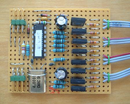
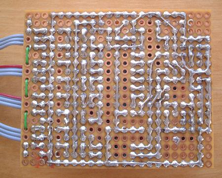
Figure 3. The component and solder sides of the module.
Serial communication protocol
The serial communication is 9.6 kbaud, 8 bits, no parity. A command sequence to a module consists of an address byte followed by one command byte. The "set pulse width" command also has one data byte. The "pulse" command generates a pulse with a default length of 0.3 s. The pulse length can be changed individually for each port with the "set pulse width" command.
Figure 4. Serial command protocol.
PIC program
The PIC processor program for the decoder can be found here:
The device address must be changed for each module to be built. The program given here has device address 0x00. If you use the .asm file, the address is defined in the beginning of the program. In the .hex file, you find 0x0C00 at position 0x003E and position 0x0047 in the code. The two lower hex digits is the device address. The values can be changed directly in the hex code with e.g. IC-Prog. Note that bit 7 in the device address must be 0.