Schematic
Figure 1. Decoder schematic.
The component values are generally not critical. I have chosen 100 kOhm as pull up resistors on most inputs because I happened to have a lot of them at home. Any value between 10 k and 220 k will be OK. The RB3 input should have a lower pull up resistor since that pin has a much higher leakage current. This input is also more sensitive to noise since it is not clamped internally in the PIC processor. It is therefore clamped with the zener diode V1. The capacitors C3 and C4 are decoupling capacitors and their size doesn't matter much.
The crystal should be 20.000 MHz and the two capacitors C1 and C2 should be in the range 15-47 pF.
Decoder circuit board
I build the decoders on Veroboard. I need too few of them to justify the manufacturing costs for a real circuit board. I have built six decoders so far. Here is a picture of one of them:
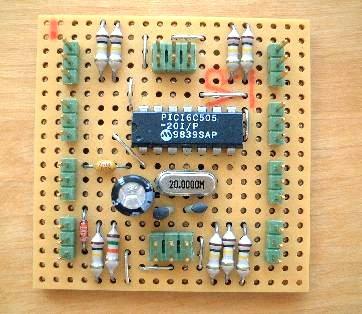
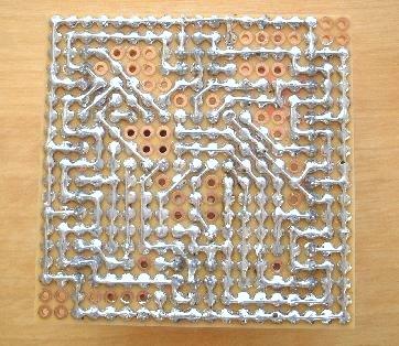
Figure 2. Decoder circuit board.
Connections and component placement is shown in the figure below (solder side view).
Figure 3. Component placement and connections, seen from solder side.
Decoder program
The PIC processor program for the decoder can be found here:
The program decodes all eight inputs in parallel, and queue them up if necessary. If the same code is detected repeatedly on the same port, it is only transmitted once every second, to avoid blocking the other decoders in the system.
Serial protocol
The serial protocol is 9600 baud, 8 data bits, no parity, 2 stop bits.
The most upstream decoder in the chain sends out a 3-byte message once every 5 ms. The message is either an IDLE message or a VALID message. The message format is as follows:
| Byte no: | VALID message: | IDLE message: |
| 0 | Sent as 0x01 by the originating decoder, incremented with 2 by each forwarding decoder. | Sent as 0x00 by the originating decoder, incremented with 2 by each forwarding decoder. |
| 1 | IR detector port number on the decoder (0-7). | 0xff |
| 2 | Received code from the loco. | 0xff |
A downstream decoder will always forward the VALID messages. If it has received data on one of its IR detector ports, it will replace an IDLE message with a VALID message, otherwise it will forward the IDLE messages too. Each downstream decoder increments byte 0 of all forwarded messages by 2. In this way, byte 0 of a VALID message coming out from the most downstream decoder will contain (decoder number * 2) + 1, where the decoders are numbered from 0 and up starting with the most downstream one. Byte 0 of the IDLE messages will contain 2 * (total number of decoders - 1).
I have chosen to let the most upstream decoder generate the IDLE message, but it is also possible to connect the serial input of the most upstream decoder to the serial data out from the computer (after appropriate translation of the voltage levels). In this case you should send one byte containing 0x00 each time you want to read the decoders. The VALID messages will be the same as described above, but the IDLE messages will only contain byte 0 in this case. The PIC program supports both methods.
The decoders use inverted data on the serial lines, i.e. a '1' is represented by 0 V and '0' is represented by +5 V.
Verification
The six decoders have been tested and operate as expected.
I have also verified the decoder program through lots of simulations. I used the MPLAB simulator for the initial tests, but it can only simulate one PIC processor at a time, it is difficult to write stimuli for it, and it is slow. Therefore I wrote my own simulator in C++ for the main simulations. The simulations showed that the system is capable of handling a little over 100 new VALID messages per second without problems. This means that one chain of decoders should be sufficient even for a large layout.