Introduction
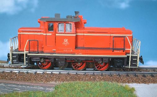
The Märklin 2890 train set models a freight train from German Federal Postal Service (Deutsche Bundespost). The set contains one Class 260 (V60) diesel locomotive, four freight cars and one post truck. The locomotive has an SFCM motor (Small Flat Commutator Motor) and is equipped with an electronic direction relay.
Figure 1. The Deutsche Bundespost Class 260 diesel from Märklin 2890 train set.
The models with SFCM motors have previously required HAMO magnets and third party decoders like e.g. ESU LokPilot to be converted to fully regulated digital operation. With the introduction of the Märklin conversion kit 60903 in June 2003, Märklin offers an in-house alternative for the conversions. The 60903 kit is more expensive than the HAMO magnet + LokPilot alternative, and you can have different opinions on whether the Märklin solution is worth its higher price. Personally I prefer the Märklin decoders, and I have therefore waited with the conversion of my SFCM models until the arrival of the 60903 kit.
Preparing the loco
Before mounting the new parts from the 60903 kit, the old parts have to be removed. The two screws that hold the original motor plate are unscrewed, and the motor plate, field coil and rotor can be lifted out. The direction relay is held in place with a plastic mounting plate but can easily be bent loose. The wires from the direction relay to the lamp sockets and pick-up shoe are then cut and/or soldered off to remove the old parts completely. The mounting plate should be removed since the new decoder is too thick to fit in it, and the lamps should also be removed.
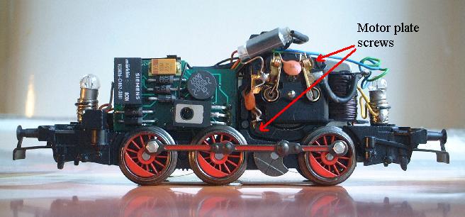
Figure 2. The opened locomotive.
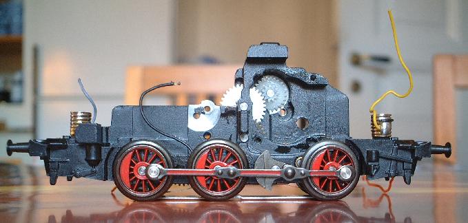
Figure 3. The locomotive stripped from its old parts.
Mounting the motor parts
The new rotor and field magnet can easily be put in place.
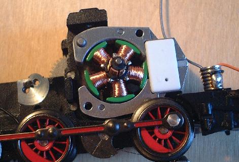
Figure 4. New rotor and field magnet put in place.
The motor plate is then mounted, and secured with the two screws that come with the kit. The solder point bracket that comes with the kit should be mounted with one of the screws, preferably the upper one. The lower screw is a little bit too long, and will block one of the cog-wheels when tightened. The solution is to use a washer, see pictures below. The screws supplied with the kit are M2x12. If you use an M2x11 screw instead you can skip the washer.
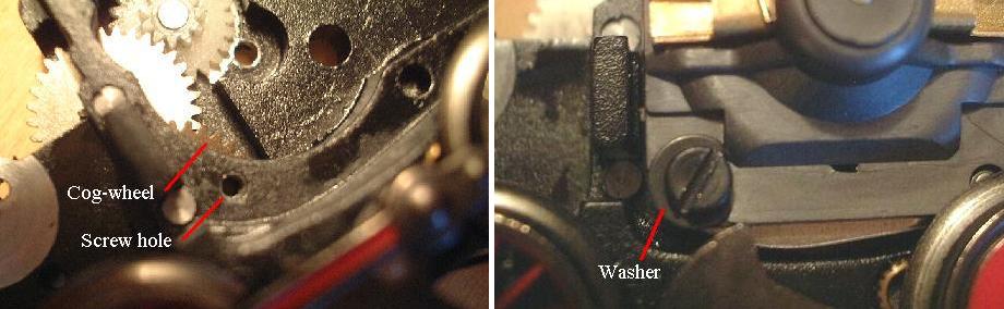
Figure 5. One of the cog-wheels may be blocked by the lower motor plate screw. The solution is to use a washer.
When the motor plate is in place, you insert the two graphite brushes. Test that the motor runs freely before you go on with mounting the electronics.
Lamp sockets
The new decoder supplies the lamps with constant 20 V DC (provided that the lamps are turned on with the Function of course). The original lamps are designed for operation with AC, with a voltage between 7 and 16 V. If you keep the old lamps they will rapidly wear out in digital operation because of the higher voltage. The kit therefore contains two light bulbs with 22 V rating and two lamp sockets. The new lamp sockets can be pressed down into the old ones.
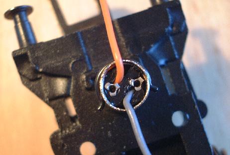
Figure 6. New lamp socket mounted inside the old one.
Noise suppression capacitors and chokes
For suppression of noise, there should be three 1 nF capacitors and two chokes. One capacitor is already mounted between the two motor brushes. The two other capacitors should be soldered between each motor brush connection and the chassis (i.e. solder point bracket at the upper motor plate screw). The two noise suppression chokes should be soldered between the motor brush connections and the motor output wires of the decoder.
Mounting the decoder
The wiring of the decoder is described in the manual that comes with the kit. Start with connecting the red wire to the pick-up shoe wire, and the brown wire to the chassis/solder point bracket, then connect the orange wire to the orange wires of the lamp sockets. I recommend to keep all wires short and to protect all solderings with pieces of shrinking tubing. If you don't have shrinking tubing you can use the two pieces of isolating tubing supplied with the kit and peel off sleeving from a wire if you need more.
Now you connect the blue and green motor wires to the two chokes. If you want a certain default direction for the loco you should first connect the wires provisionally to test out the desired direction. Then you make a provisional connection from the grey lamp socket wires to the grey and yellow wires of the decoder, and test that the lights are on in the forward direction. If not, you let the yellow and grey wires change places before you make the permanent connection.
The new decoder does not need to be secured, it will stay in place anyway. I have used isolating tape to secure the wires so that they are out of the way when I mount the loco body.
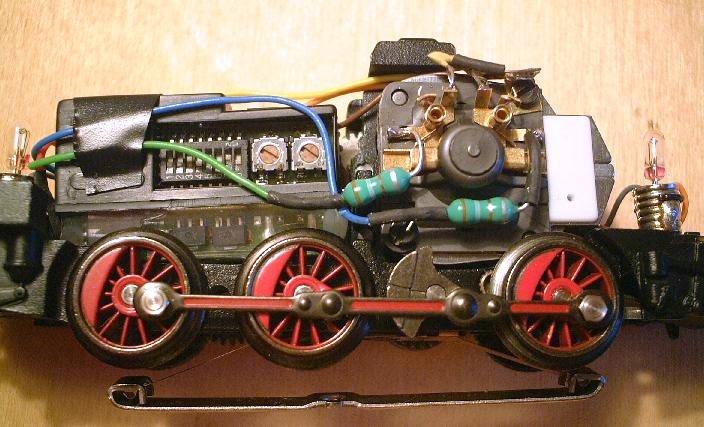
Figure 7. New decoder installed.
Result
The result is a loco which operates with the same excellent performance that we have been used to with other regulated Märklin decoders.